
Model B
Model A Ford Garage
Pertronix Ignitor Distributor
Timing Procedures

 fordgarage.com
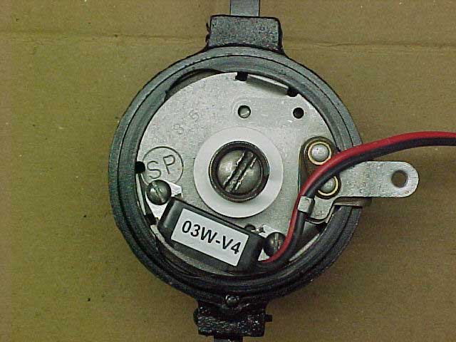
The following pics show how to properly set the initial timing on the Model B Ford distributor with a Pertronix Ignitor electronic ignition.
The Pertronix conversion replaces the mechanical points and condenser with a solid state Hall effect transducer which switches the primary current to the coil on and off. The transducer reacts to reversals in magnetic field strength (the Hall effect) induced by cobalt magnets. The magnets are embedded in a plastic ring which attaches to the stock distributor cam.
The Hall effect transducer contains an electronic latching trigger, and the dwell time is controlled by two sets of magnets in the cam ring. Four north pole out, and four south pole out magnets trigger the on-off dwell time. The dwell is set at 28 degrees internally in the transducer and is not adjustable.
Regular firing is often not possible on Model B distributors with conventional mechanical points and worn shafts or bushings. The Model B distributor is known for the excessive wear and slop which develops between the main shaft and the movable upper cam shaft due to the small diameters and surface area between the two shaft pilots. This clearance and wear changes the geometry and increases (amplifies) the variation in the point arm movement and spark timing in a stock point ignition set up.
The mounting position of the transducer on the upper plate is critical to assure triggering at the proper position of the rotor relative to the distributor body electrode throughout the range of static plate adjustment.
The transducer mounting position on the upper plate was designed so that the rotor-to-body electrode relationship remains correct, no matter what position the static upper plate is re-adjusted to after initial timing is set.
Model B upper plates are not available new but originals can be modified to properly position, orient, and mount the Ignitor transducer. Plate conversion service is available on inquiry.
Timing Procedure
 fordgarage.com
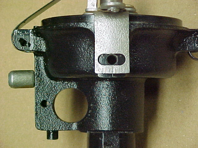
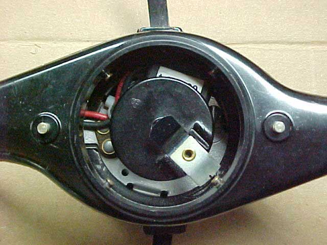
1) The pic above shows the initial timing position of the upper plate to the cast housing. The plate must be centered on the hash mark on the casting before adjusting the cam and rotor. This can be done on the bench. All the subsequent cam and rotor adjustments are made with the distributor on the engine.
Model B Timing Cover Instructions:
 fordgarage.com
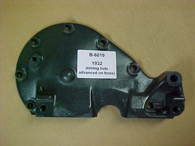
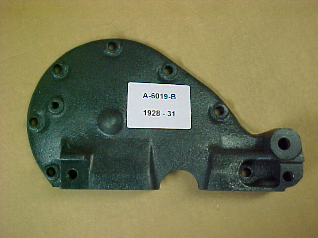
2) Shown above is the Model B front timing cover. The timing pin hole is located at the top of the oblong boss. Only use the instructions in Section 3) below for the Model B cover.
 fordgarage.com
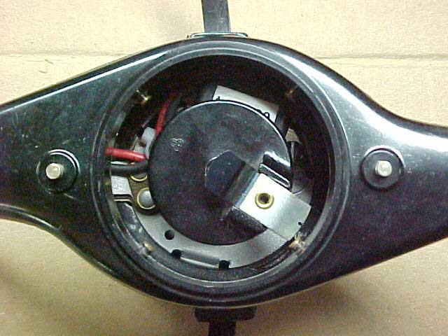
3) The pic above shows the initial timing position of the rotor when timed with a Model B front timing cover. The Model B timing cover is shown in Section 2), and has the timing pin hole located 19 crankshaft degrees BTDC. At that point, the center of the rotor should be centered on the electrode in the distributor body.
- Center the plate with the hash mark on the casting.
- Loosen the distributor cam screw slightly.
- Insert the timing pin in the front cover and find the dimple in the cam gear. This is 19 crankshaft degrees BTDC.
- Rotate the cam and rotor around clockwise until the rotor is centered on the number one cylinder electrode in the distributor body. Turn only clockwise to remove all lash from the setting. Use a tight fitting distributor body.
- Secure the cam screw with a screwdriver and cam wrench without disturbing the cam position on its shaft.
- After the rotor is positioned and secured, assemble the cap and start and run the engine.
- The upper plate may then be moved to advance or retard the initial timing to suit conditions. Each hash mark is equal to 2 crankshaft degrees. Move the plate clockwise to advance the timing, and counter-clockwise to retard the timing.
Model A Timing Cover Instructions:
 fordgarage.com
4) The pic above shows the Model A front timing cover. The timing pin hole is located in a round boss. When the timing pin is in the dimple in the cam gear, the crankshaft is at 'zero' degrees and the number one piston is at TDC. Use the instructions below only for timing the Model B distributor with the Model A timing cover shown above, or with the Model A 'service' timing cover with the timing pin hole at the bottom of the boss.
Note:
These instructions below also apply to the special case of a G28T engine using the original G28T components including timing gear cover, crankshaft gear, and camshaft gears. The G28T camshaft timing gear has two timing marks. One mark on the camshaft gear is the dimple for the timing pin. The other mark (scribe) is 9-1/2 degrees before the separate camshaft gear-aligning mark for use with the crankshaft timing gear.
The G28T timing cover is functionally equivalent and interchangeable with a Model B cover, but the spark is timed identically to a Model A when using with a G28T camshaft gear with a G28T timing gear cover.
 fordgarage.com
5) The pic above shows the initial timing position of the rotor when timed with a Model A front timing cover. The Model A timing cover is shown in Section 4) above, and has the timing pin hole located at number one piston TDC (0 crankshaft degrees). At TDC, the trailing edge of the rotor should be aligned with the number one cylinder electrode in the distributor body.
- Center the plate with the hash mark on the casting.
- Loosen the distributor cam screw slightly.
- Insert the timing pin in the front cover and find the dimple in the cam gear. This is TDC ('zero' crankshaft degrees).
- Rotate the cam and rotor around clockwise until the trailing edge of the rotor is aligned with the number one cylinder electrode in the distributor body. (The 'trailing edge' is the lower edge shown in the pic above, since the rotor turns in a counter-clockwise rotation when running.) When manually setting the rotor position, turn only in clockwise rotation to remove all lash from the setting. Use a tight fitting distributor body.
- Secure the cam screw with a screwdriver and cam wrench without disturbing the cam position on its shaft.
- After the rotor is positioned and secured, assemble the cap and start and run the engine.
- The upper plate may then be moved to advance or retard the initial timing to suit conditions. Each hash mark is equal to 2 crankshaft degrees. Move the plate clockwise to advance the timing, and counter-clockwise to retard the timing.
More related information on Ford Garage:
- For more Model A & B related information, use the Site Search box at the top or bottom of this page.
- Model B & Model 46 Distributor Design Details
- Model B & Model 46 Distributor Advance Operation
- Model A Remund Pertronix Electronic Ignition Instructions
- Model A & B Engine Cam/Valve and Ignition/Spark Timing Discussion
- Model A, B, & Model 46 Camshaft Gear Timing Cover Differences
- Model A & B Ignition Components Interchange Chart
- Model A Condenser Capacitance
- Model A & B Condenser Details
- Model A Distributor Lower Plate Wiring Solution
- Model A Nu-Rex Centrifugal Spark Advance Unit
- Model A Phillips Automatic Spark Control Unit
Vince Falter
December 2003
