
Model A
Ford Garage
Distributor Lower Plate Wiring Solution

 fordgarage.com
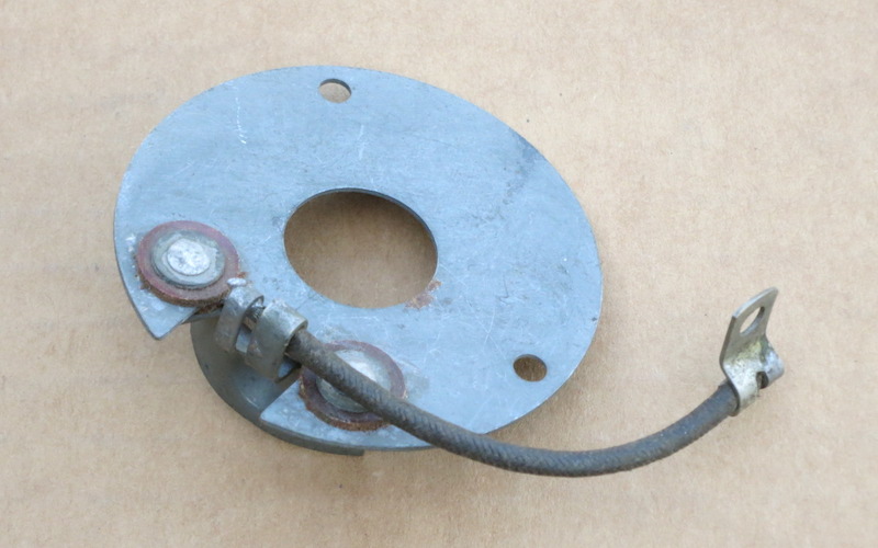
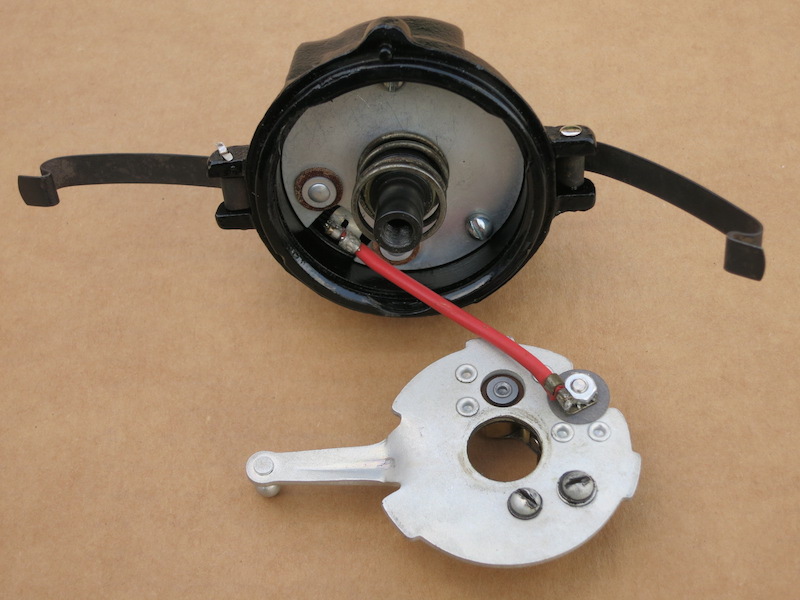
Pictured above for reference is an NOS lower distributor plate showing the relative positions and orientation of the 3-1/8 inch long wire and flag terminal which connects to the stud of the movable point arm on the upper contact plate.
The Problem:
The Model A distributor reliability is frequently maligned due to the 'unreliable' nature of the wiring between the lower plate and the moveable contact point mounting stud on the upper plate.
The original Ford design consisted of a short length of cloth-covered rubber-insulated wire which is crimped and soldered to the bus bar on the lower plate.
There is a flag terminal at the other end which is attached with a nut to the stationary post of the movable upper contact point arm.
This will lead to insulation cracking and a direct short to ground, especially if any moisture is held in the cloth-covered wire insulation.
The chance of insulation cracking is also increased due to the fact that the wire is flexed whenever the spark advance lever on the steering column is moved.
A direct short prevents the primary ignition circuit from 'breaking' and prevents the collapse of the field in the coil (which is necessary to produce the spark). A wire short has the same effect as pushing the pop-out switch to disable the ignition.
 fordgarage.com
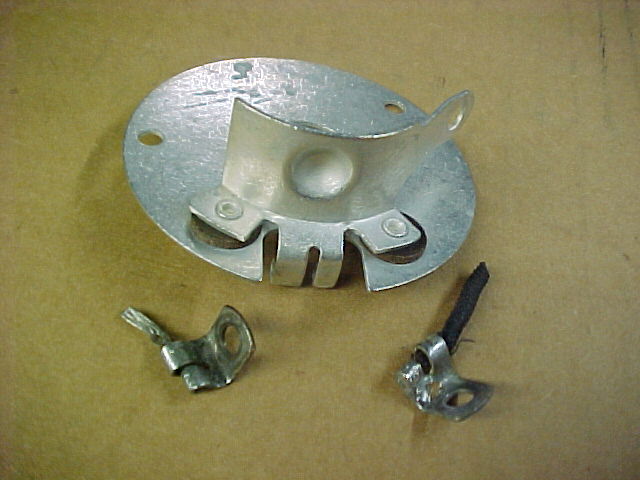
Pictured above is a restored original lower plate and two original wire terminal flags. Note the remains of the original high-count fine-strand wire and the original cloth-covered rubber insulation.
Most modern automotive wire is vinyl covered, has fewer strand count, and is even less flexible than the original Model A wire pigtail.
The shape of the flag terminals is also important. The flags shown are the correct shape to mount in the small recess space on the bottom of the upper plate, and to avoid contact and ground-out with the upper plate, distributor casting, spring, or any other ground path. The original Ford design includes the 90 degree bend shown in the flag.
The Solution:
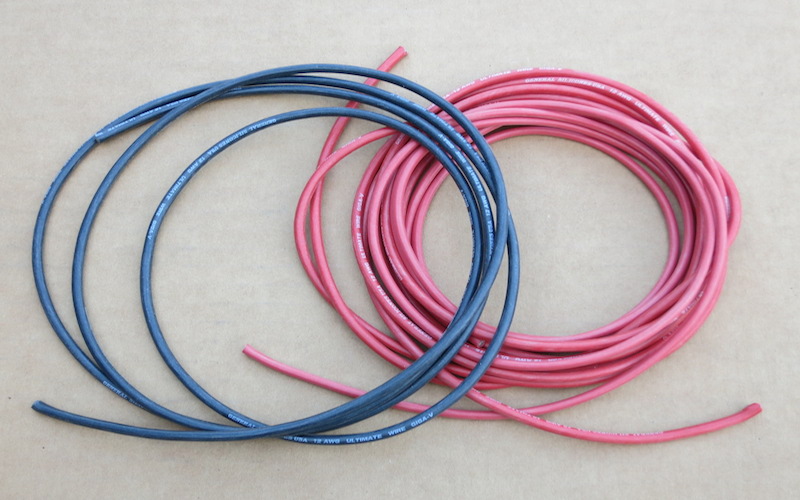
Pictured below is the solution to the heat, cracking, and shorting problems. Shown is an extra-flexible fine-strand tin plated copper ignition wire with silicone rubber insulation.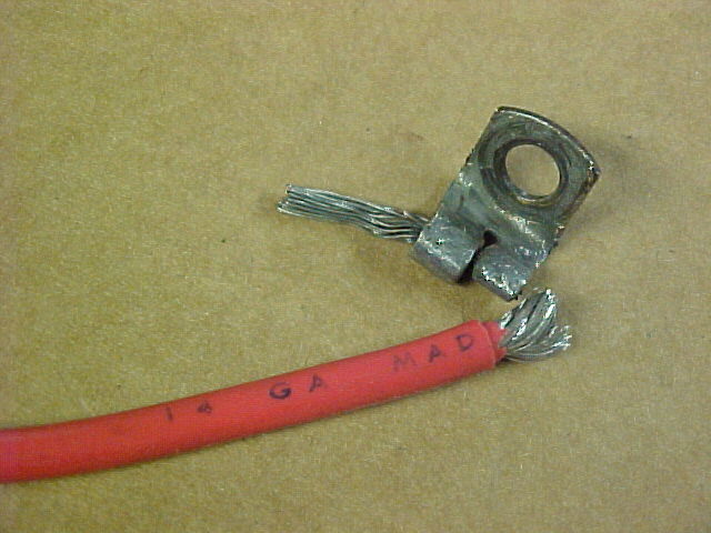 fordgarage.com
This type of high temp flexible wire is available in black or red in 12, 14, or 16 wire gauge at many hobby stores that specialize in radio control cars and airplanes.
This specialty wire has very good flexibility and durability compared to regular automotive wire, and the insulation can also withstand much higher and lower temperatures without melting, hardening, cracking or other damage.
 fordgarage.com
The correct overall length of the wire assembly is 3-1/8 inches from the end of pigtail to the end of stationary terminal.
Do not make the wire longer than intended, as that will also lead to wire damage and failure. Be sure to carefully solder the wire to the terminal and flag ends to ensure a robust mechanical and electrical connection.
This improved wire can be used to restore original lower plates, and they will be more robust than any original or reproduction plates. It is also more reliable than the so called 'wireless' upper and lower plates which can easily develop poor connections in the sliding brass contacts.
I also use modern flexible high temperature silicone ignition wire to replace the original cloth-covered rubber wire in the pop-out armored cable. This is a very robust solution using modern low and high temperature insulation materials which were not available in 1928.
In addition, it is recommended to also use a 'modern' burn-out proof (polyester internal insulation) condenser (capacitor) of proper 0.30µF capacitance. This modern condenser can reliably withstand the temperatures inside the cast iron distributor from the nearby exhaust manifold.
 fordgarage.com
More related information on Ford Garage:
- For more Model A & B related information, use the Site Search box at the top or bottom of this page.
- Model B & Model 46 Distributor Design Details
- Model B & Model 46 Distributor Advance Operation
- Model B & Model 46 Pertronix Ignitor Distributor Timing Procedures
- Model A Remund Pertronix Electronic Ignition Instructions
- Model A & B Engine Cam/Valve and Ignition/Spark Timing Discussion
- Model A, B, & Model 46 Camshaft Gear Timing Cover Differences
- Model A & B Ignition Components Interchange Table
- Model A Condenser Capacitance
- Model A & B Condenser Details
- Model A Nu-Rex Centrifugal Spark Advance Unit
Vince Falter
May 2001
