

Model A & B
Ford Garage
Fan Blade Differences
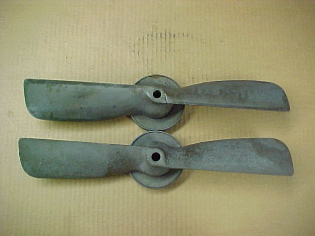
The following pics show two styles of the Model A and Model B Ford engine cooling fans. The original design used by Ford from 1928 to 1931 consisted of a two piece stamped steel construction as shown in the top of each pic.
Each thin piece of stamped steel formed the front of one blade and the back of the opposite blade. The two halves were seam welded around the perimeter and had an odd overlap condition where they came together at the front of the hub.
The Model A fan was very prone to cracking and was replaced with an improved construction Model B style. The Model B fan was also known as the Holley design fan.
At a glance it looks like every other fan, but it is a much improved construction, and was Ford's fix to the fan cracking problem which was becoming apparent at that point in time. These improved Model B fan blades are made from a single piece steel stamping.
In 1933 the four blade fan was introduced on the Model 46 four cylinder, and this fan then became the Service replacement part for Model A's and B's.

 fordgarage.com
The Model A is shown on top, Model B on bottom. The fatigue cracking of the Model A fan usually originates at the blade root where the overlap is visible in front view, though ultimately either blade can crack.
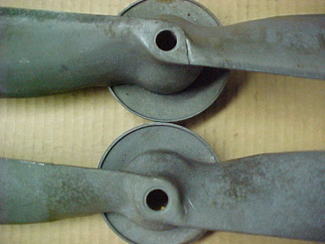
The crack initiation point is visible at about the 4:00 position from the centerline in the upper fan. These Model A fans crack there for a number of reasons.
First, the pieces of the Model A fan are thin steel stampings with the raw sheared edge located in cyclic tension at the point of highest stress at the blade root.
Second, the two piece seam welded construction allows moisture and rust to form inside the blade halves, and this can both weaken the fan structurally and can cause mass imbalances which increase the stresses at the blade roots. Both effects hasten the crack initiation and ultimate failure.
 fordgarage.com
Close up pic above shows how the improved Model B one-piece stamping (on bottom) is wrapped over itself in the center five inches of the fan, and how the leading edges at the root consist of a radiused surface formed by the hemmed heavier gauge steel. Also, there are no sheared edges or sharp corners anywhere in the critical center five inches of the Model B fan to act as stress raisers and crack initiation sites.
 fordgarage.com
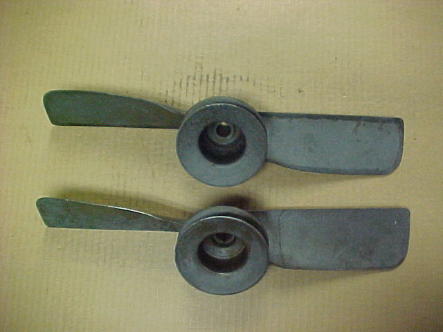
Backside view showing the Model A on top and the Model B on bottom. Note the perimeter seam welded construction on the upper Model A fan.
 fordgarage.com
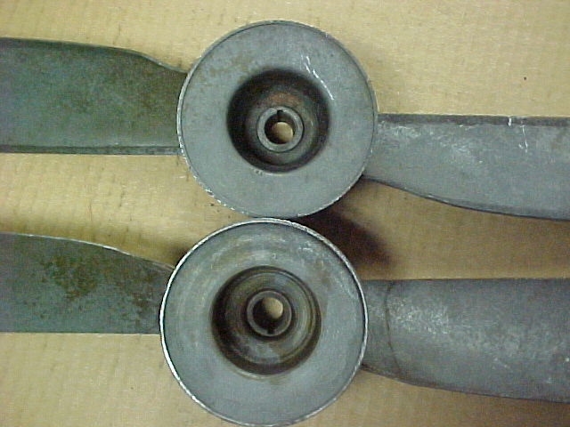
The close up above shows the back sides. Note the construction of the Model B fan blade (bottom) and how the doubled over metal is electric welded about 2-1/2 inches out from centerline. This is how the critical blade-root zone is designed for increased strength and protected against fatigue failure.
Additionally, since the Model B fan is a one-piece blade construction, there is no place for moisture to form rust and create mass imbalances out on the blades where it would affect the fatigue life, though rust can form on the inside of the hub area in both styles.
More related information on Ford Garage:
- For more Model A & B related information, use the Site Search box at the top or bottom of this page.
- Model A & Model B Water Pump Shafts and Fan Hubs
- Model A NOS Original Water Pump Shaft
- Model A Reproduction Two-Piece Water Pump Shaft
- Model 40 & Model 46 Four-Blade Radiator Cooling Fans
- Model 40 & Model 46 Four Cylinder Radiator
- Model B & Model 46 Water Pump Housings
- Model A Cragar Overhead Valve Head Water Pump
Vince Falter
October 2000
