
Model A
Ford Garage
Zenith Carburetor
Jet Sizes & Flow Rates
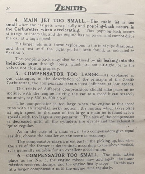
This (lengthy) page is best viewed on a Desktop or Laptop computer
The function of a carburetor is to meter, mix, and maintain both air and fuel quantities in a prescribed ratio across a range of engine RPM and operating conditions.
The carburetor's air intake horn, venturi, throttle bore, and jet circuits are all sized in a coordinated manner to suit a specific application by the carburetor designer. This is done to create and maintain the correct air/fuel mixture ratio for a given engine size and speed range, as well as for fuel type and quality.
Jet Flow Test Theory
The various jets in a carburetor design are sized to deliver the needed fuel quantities based on the running conditions and requirements of the carburetor and engine.The flow testing of jets is a quantitative comparative measurement method to enable the comparison of jets to each other, or to a standard flow rate specification.
Important Fact to Comprehend:
Water testing jet flow values at 36" head pressure have no direct correlation to the actual fuel flow or fuel consumption quantities through the identical jet in the carburetor of an actual running engine!
Cut to the Chase:
Ford Garage ~ Model A Zenith ~ Jet Flow Test Targets | ||||
| Water Flow Rate Recommendation cc's/min (ml/min) (@ 36" Head Pressure) |
Idle Jet A-9542 (manifold vacuum on Idle Jet) |
Main Jet A-9534 (venturi suction on Main Jet) |
Compensator Jet A-9575 (atmospheric pressure on fuel, on both sides of Compensator Jet) |
Cap Jet A-9538 (venturi suction on Cap Jet) Cap discharges Comp + GAV |
|---|---|---|---|---|
| Standard Elevation <5000 ft above sea level ethanol fuel era |
50 - 60 target enables greater idle air mixture control (leaner for 100% gas) (richer for E10 blend) |
148 - 152 target enables greater GAV utilization |
148 - 152 target enables greater GAV utilization |
200-300 target enables greater GAV contribution |
| Higher Elevation 5000+ ft above sea level ethanol fuel era |
50 - 60 target enables greater idle air mixture control (leaner for 100% gas) (richer for E10 blend) |
125 - 129 target enables greater GAV utilization |
125 - 129 target enables greater GAV utilization |
200-300 target enables greater GAV contribution |
Read on, for an In-depth Discussion:
The Model A carburetor was designed and developed for Ford by Zenith-Detroit, but was supplied in production by both Zenith and Holley (under license from Zenith). According to archive research conducted by George De Angelis in the 1970's, Zenith supplied about two-thirds of Ford's requirements, with Holley supplying the rest.
In my own experience in the Midwest, Holley prevalence seems to outnumber Zenith slightly, perhaps 60/40.
Holley-built carburetors and castings are usually marked with a Holley 'H' identification cast inside the bowl on each casting as well as markings on some other component parts, and also usually carry either a Zenith-2 designation cast on the exterior of the float bowl, or a raised 'H' cast on the exterior of the upper and lower castings, at the Venturi. Additionally, Holley upper castings are not through-drilled on the inboard side for the throttle shaft.
All the component parts from both Zenith and Holley carburetors are interchangeable and can be freely mixed and matched in practice.

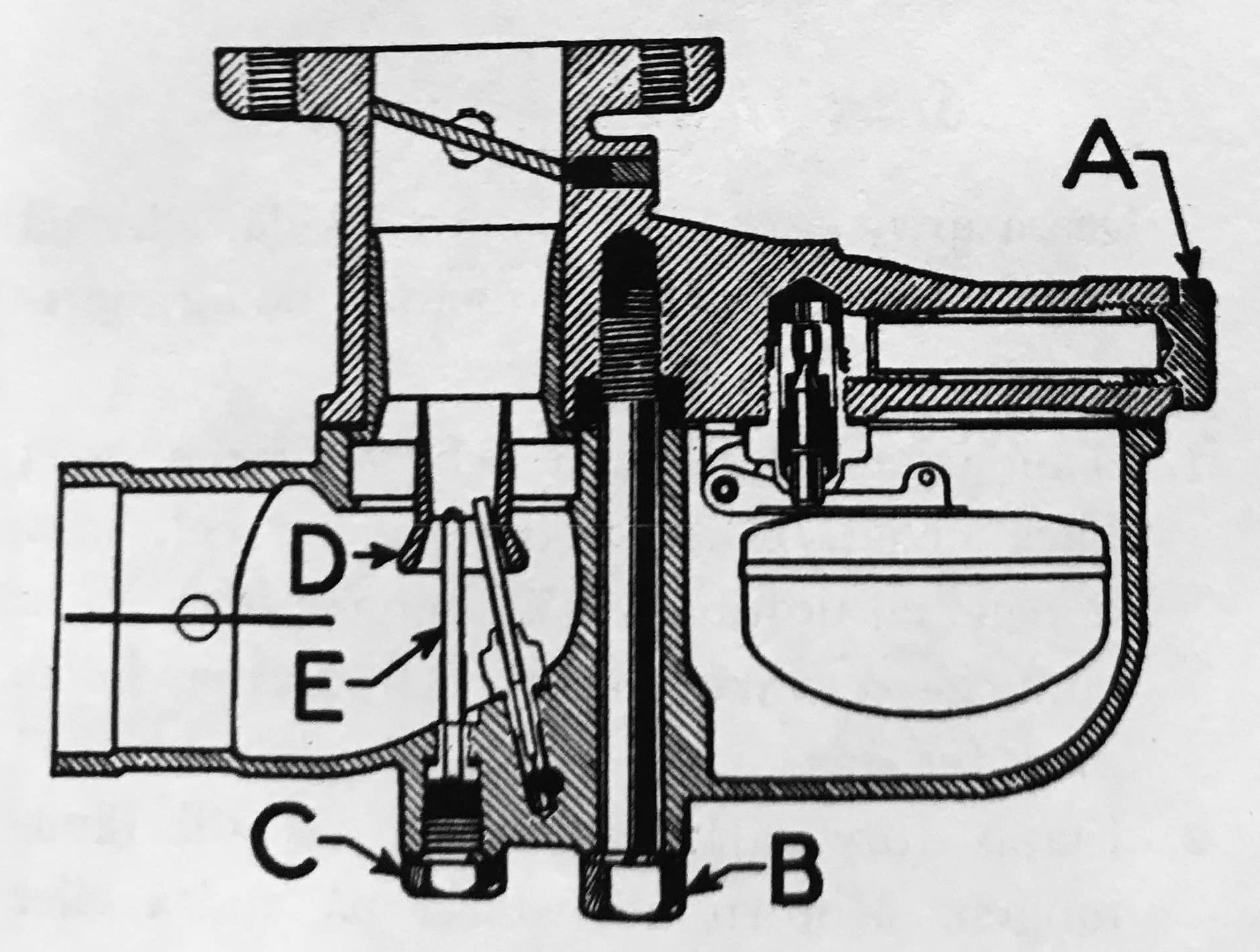
The Fuel Strainer is marked 'A'.
The Main Assembly Bolt is marked 'B'.
The Drain Plug is marked 'C'.
The Inner Venturi is marked 'D'.
The Main Jet is marked 'E'.
Also note the DV inline Cap Jet having the jet orifice at the bottom rather than the top of the jet assembly.
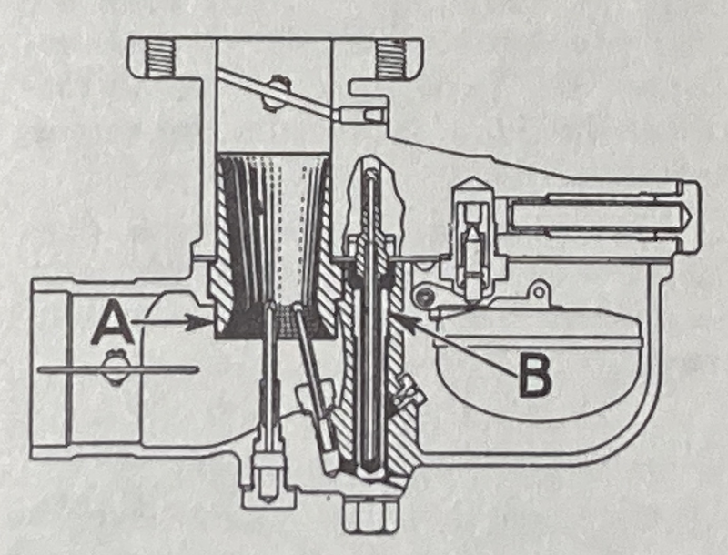
The Single Venturi is marked 'A'.
The added Idle/Secondary Well is marked 'B'.
Also note the SV offset Cap Jet having the jet orifice at the top rather than the bottom of the jet assembly.
Zenith Theory of Operation
Both Model A and B Zenith carburetors are updraft design, and are entirely vacuum and fuel-gravity operated. There are no active pistons, plungers, pumps, actuators, or other features in their operation aside from the throttle plate, the choke plate, and the Gas Adjusting Valve (GAV) knob.The Model A Zenith carburetor has three jet circuits which consist of an Idle Jet circuit, a Compensator Jet (measuring/metering orifice) circuit, and a Main Jet circuit. The so-called Cap Jet is not a measuring or metering jet circuit per se, though it is acted on by Venturi suction. The Venturi was also sometimes referred to as a 'Diffuser' in Ford and Zenith literature.
Airflow into the carburetor is controlled by the Air Shutter (Choke Plate) position in the lower casting. The Choke Plate is normally open, except when manually applying (closing) the choke during cold starting. Zenith company literature also sometimes referred to the Choke as the 'Strangler'.
Airflow through the carburetor is subsequently controlled by the Throttle Plate position in the upper casting. The flow of the air/fuel mixture through the Venturi and into the throttle bore increases as the Throttle Plate opens, resulting in increased engine speed. The size of the Venturi determines the maximum volume of air which can be passed through the carburetor.
The airflow through the Venturi during off-idle and open-throttle conditions determines the amount of suction applied to the Main and Cap Jets at the Venturi.
The limited airflow past a near-closed Throttle Plate determines the amount of engine manifold vacuum applied to the idle mixture discharge orifice (Zenith called it the Priming Hole) at the edge of the Throttle Plate in the throttle bore. The Idle Stop Screw on the Throttle Lever sets the near-closed Throttle Plate idle position, and thus the resulting idle RPM.
The Idle Jet assembly flows fuel according to the engine manifold vacuum above the Throttle Plate only when the Throttle Plate is nearly closed. The Idle Jet ceases to flow fuel as the Throttle Plate is opened further, and as manifold vacuum decreases on the Priming Hole in the throttle bore at the edge of the Throttle Plate.
The air used in the idle air mixture circuit is made up of the air admitted through the bowl vent by the air mixture screw needle, combined with the larger volume air flowing past the nearly-closed Throttle Plate in the upper casting bore. The primary purpose of the mixture screw needle is to regulate the suction applied to the fuel which is fed through the Idle Jet assembly itself.
The Idle Air Mixture Screw (Needle) meters and mixes outside air (via the carburetor bowl vent) with the fuel drawn through the Idle Jet assembly (lifted through its siphon tube suspended in the Compensator/Idle/Secondary Well), as well as regulating the actual suction applied to the Idle Jet and siphon tube assembly by the manifold vacuum at the Priming Hole.
The Air Mixture Screw Needle is effectively a controlled air/vacuum leak in the idle circuit's fuel drinking straw (the Idle Jet Siphon Tube).
The Siphon Tube of the Idle Jet assembly extends down into the machined iron Compensator/Idle well in the case of a Double Venturi carburetor. It extends down into the brass Secondary Well in the case of a Single Venturi carburetor.
The actual Idle Jet assembly's Orifice is located at the top of the brass Idle Jet assembly (which is screwed into the upper iron casting).
That idle air-fuel mixture is discharged through the Priming Hole (idle discharge orifice) in the upper iron casting throttle bore (above the Venturi, and at the Throttle Plate) during near-closed throttle conditions, and at engine speeds less than 550 RPM.
The Compensator/Idle/Secondary Well is full of fuel when the engine is idling or at a steady state condition. It provides a reserve for both acceleration when the throttle is opened off-idle, as well as for a sudden return-to-idle. The Well level can be reduced slightly during acceleration according to the Comp Jet flow limit. The fuel into flow the Well is diverted from the Idle Jet to-and-through the Cap Jet during acceleration and open throttle by the increasing suction of the Venturi (at engine speeds greater than 550 RPM).
In the case of the Double Venturi carburetor, the higher air flow speed between the inner and outer Venturis changed the responsiveness of the Cap Jet favorably at off-idle conditions without using a separate (off-idle) buffered fuel reserve in a Secondary Well for the return-to-idle circuit transition.
Ford and Zenith (and Holley) ended production of the Double Venturi design beginning in June 1928 due to patent infringement claims brought by Stromberg (which Ford later lost in 1934). Stromberg did not have any Model A business at that time, but later became a Ford supplier using the Stromberg double venturi designs/patents on flathead V8 carburetors in the mid 1930's.
During off-idle acceleration and open throttle operation, the brass Idle/Secondary Well maintains a partial fuel level available for use by the Idle Jet whenever the Throttle Plate is suddenly closed, quickly returning to the idle stop position (during braking, for example). This slight fuel level reserve in the Idle/Secondary Well prevents stalling during the return-to-idle circuit transition.
The Compensator (Comp) Jet (actually a measuring/metering orifice, not truly a jet) is located in the float bowl, and its flow rate into the Compensator/Idle/Secondary Well is constant and governed by its orifice size and by atmospheric pressure on both inlet and outlet sides, and is independent of Throttle Plate position or Venturi suction across a changing range of engine speeds.
The Compensator Jet maximum fuel flow is the same at all speeds, but its resulting effect is most noticeable at low speeds, or when under a load, or during acceleration.
The fuel metered by the Compensator Jet at idle (<550 RPM) supplies the Idle circuit via the Idle/Secondary Well. As the suction at the Venturi increases with increased throttle opening and engine speed, the fuel which passes through the Compensator Jet is biased away from the idle circuit, and is discharged through the Cap Jet orifice into the Venturi air flow.
The Compensator Jet's maximum fuel flow is limited by its orifice size and atmospheric pressure in the float bowl, not by the manifold vacuum on the Idle circuit or by the applied Venturi suction on the Cap Jet. This is due to a small drilled vacuum breaker (vent hole) in the top of the Secondary Well in a Model A, or in the case of a Model B a small drilled hole in the threaded barrel of the Idle Jet.
The Gas Adjusting Valve (GAV) is an adjustable needle and seat which meters additional fuel directly from the float bowl into the iron well supplying the Cap Jet, but bypasses the Compensator Jet orifice restriction. The added fuel flow rate is manually controlled by the driver of the vehicle using the needle control knob at the head of the choke control rod.
The Cap Jet (so-called 'jet') is more of a discharge tube (outlet orifice) located at the Venturi for the idle-to-open throttle transition. It does not meter or measure any fuel itself. As the suction at the Venturi increases with throttle opening and engine speed, the Cap Jet combines and discharges all of the fuel previously metered and provided by both the Compensator Jet and the GAV control needle.
The Main Jet is the high speed jet and flows fuel directly from the float bowl according to its jet orifice size, and according to the direct suction applied to the Main Jet orifice at the Venturi. The fuel flow increases as the air flow and suction in the Venturi increases with throttle opening and engine speed.
In a Model A Zenith carburetor, the total fuel delivered in off-idle and open throttle conditions is the sum of the fuel metered by the Compensator Jet to the Cap Jet, plus the fuel supplied by the Main Jet, plus any additional fuel supplied by the GAV.
As-found carburetors are often a mixed bag of various mismatched Double Venturi and Single Venturi castings and components resulting from 90 years of repairs, rebuilds, and modifications. Additionally, mismatched parts from both Zenith and Holley are frequently seen co-mingled in an as-found carburetor.
The Model B Zenith carburetor has three similar circuits to those described above, as well as an added Power Jet (measuring/metering orifice) circuit. The Power Jet itself is located inside the float bowl and meters additional fuel during open throttle conditions and positions, and according to intake manifold suction in the throttle bore above the Venturi (not according to the airflow suction at the Venturi).
Fuel flows through the Power Jet into a drilled Power Jet Tube Well in the lower iron casting, up through a Power Jet Siphon Tube, and through a #60 (0.038 - 0.042 inch) drilled Discharge Hole located just above the Venturi, and at the edge of the Throttle Plate in the upper casting throttle bore.
The suction applied to the Power Jet circuit is controlled by a slot machined into the inboard end of the brass Throttle Shaft, and which together with the shaft bore in the upper casting acts as a vacuum valve based entirely on throttle lever/shaft position.
The maximum fuel flow through the Power Jet is determined only by its orifice size and atmospheric pressure in the float bowl. This is due to a drilled #60 vacuum breaker (vent hole) in the upper iron casting, above the Power Jet Siphon Tube Well. The Power Jet Siphon Tube Well is machined in the lower iron casting.
In a Model B Zenith carburetor, the total fuel delivered in off-idle and open throttle conditions is the sum of the fuel metered by the Compensator Jet to the Cap Jet, plus the fuel supplied by the Main Jet, plus any additional fuel supplied by the GAV, plus any additional fuel provided by the Power Jet circuit.
What's up with the GAV, anyway?
The Model A and B Ford Zenith carburetors were designed with a distinctive feature. That feature is the driver-controlled Gas Adjusting Valve, or GAV. The GAV is the adjustable mixture knob inside the car, which also operates the choke control.Ford put the GAV knob inside the car so that the driver could manually vary the richness when running by adding supplemental fuel to the airstream of the carburetor (added to/through the Cap Jet). The combined air-fuel mixture drawn into the engine through the Venturi is controlled by the Throttle Plate position, via the gas/accelerator pedal (throttle control assembly).
The GAV augments the fuel which the carburetor already automatically supplies. This operator-controlled extra fuel can aid cold starting and warm-up, heavy load conditions, or make up for poor quality fuel, for example.
The Model A Zenith carburetor does not have a fast idle cam or solenoid acting on the throttle shaft lever, or have a thermostatic choke control, unlike typical 1940's-1980's carburetors. There is also no accelerator pump in the carburetor to squirt an extra shot of fuel. Pumping the accelerator pedal on a Model A has no effect or benefit when starting the engine, other than to vary the throttle plate position (further) off-idle.
The choke control, GAV knob, and hand throttle on the Model A can all be used together by the driver to set a comparably richer and faster idle condition during cold weather starting and warm-up, as the need arises.
After the engine is started and warmed up, the choke plate can be fully opened, the idle speed reduced (by hand throttle), and any added fuel from the GAV can be reduced or shut off.
It should also be stated that the GAV has no effect on the idle speed or idle quality of a properly tuned carburetor on a warmed-up Model A engine (though it is also possible for the GAV to replenish a starving Secondary Well and Idle Jet in the case of an obstructed Compensator Jet).
The Idle is a completely separate circuit and jet, and is only influenced by manifold vacuum during near-closed throttle conditions at speeds below 600 RPM.
The GAV only augments the Cap Jet, which is only influenced by venturi suction during partial and open-throttle conditions above 600 RPM.
If the GAV has an affect on the idle speed or quality, that indicates that the carburetor is set well above intended idle speeds, or that the Compensator Jet is obstructed. If the carburetor will not idle at lower RPMs, then the Idle Jet Orifice or the idle circuit (fuel or air) is likely obstructed.
Jet Numbering:
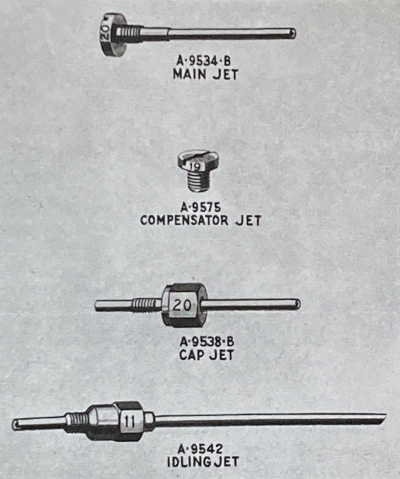
All original Model A and B Ford Zenith and Holley carburetor jets had the nominal orifice size number stamped somewhere on the jet, making identification easy. No reproduction jets have had the jet numbers stamped on them.
For example, a jet marked '18' has an orifice diameter of (18)*(0.05 mm) = 0.9 mm (= 0.0354 inches).
Jets were all machined and manufactured to dimensional requirements, however, the jets also had water flow test performance requirements which also had to be met, as indicated on the part detail drawings.
Jet Flow Water Test Pressures:
Per the original 1928 Zenith and Ford jet detail drawings, a 1 Meter (39.4 inches) head pressure of water was initially used to specify the jet flow rate test performance.
By mid 1928, Ford and many Zenith jet drawings were revised to reference a head pressure of 37-1/4 inches of water (1.35 psi) to specify the flow rate performance. The origin or significance of the 37-1/4 inches test value is not clear.
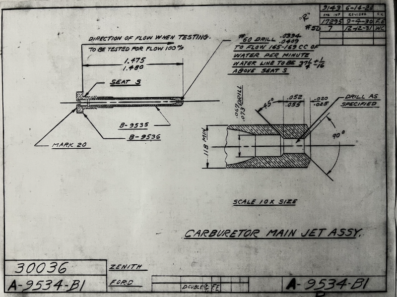 fordgarage.com
The detail drawing example above from late 1931 is fairly typical of most Model A and B jet drawings. This particular drawing also indicates that at that time jets were all to be 100% flow tested.
The flow differences through a jet will be roughly proportional to the square root of the head pressures, therefore the flow difference between a 36 inches head and a 37-1/4 inches head of water will be less than 2%.
Jet Flow Water Test Rates:
The various specifications reported for each jet in the tables below include water flow test rates and/or orifice sizes. Flow rates are expressed in cubic centimeters/minute (cc/min), which is equivalent to milliliters/minute (ml/min). Orifice sizes are typically stated in either decimal inches or Number Drill size, or occasionally as decimal millimeters.
The tables below also contain many specified size dimensions of orifices taken from original drawings, however, keep in mind that those are initial manufacturing and machining dimensions from Ford and Zenith drawings. The actual performance specified was a water flow test requirement, not a dimensional requirement.
You may also notice that some original components with the same size numbers or orifice diameters have different flow test requirements. This is based on the flow of the fuel through the differing tube geometries and lead-ins to the orifice, as well as the external air pressures acting on the fuel supply and the orifice.
Some components such as the Compensator Jet and Power Jet only flow fuel based on the direct fuel mass gravity and atmospheric pressure acting on them in the float bowl, and only indirectly according to engine suction.
Other jets like the Main, Cap, and Idle are acted on by manifold or venturi suction effectively lifting a mass of fuel through the jet, opposed by the gravity force of the fuel itself. This effect of suction versus atmospheric pressure results in different actual fuel flow rates through like-sized orifices in a running engine as well.
The specified water (not fuel) test flow rates are just the standardized water flow laboratory test conditions, and enable the ability to correlate physical jet/flow changes to observed changes in actual running engine test performance.
The water flow test values do not have any direct correlation to the actual fuel flow rates through the jets during actual engine operating conditions.
The actual operating fuel flow rates in the carburetor of a running engine are determined by orifice sizes and the particular pressures acting on the fuel at each of those various jets, i.e. atmospheric pressure, manifold vacuum, or venturi suction.
 fordgarage.com
Understanding the measured test flow rates through the jets is a way to make quantitative changes for evaluation, and for comparison of the resulting engine performance changes.
If the performance is not satisfactory, knowing the initial jet flow rates gives a basis for further modification to the jet flow rates and subsequent re-evaluation. Treat any physical size dimensions of the jet as additional interesting information.
You can make comparisons and conclusions from the data below, and establish your own personal flow rate targets. Hopefully this information will be helpful in guiding your carburetor rebuilding and tuning activities.
Summarized below are the jet flow specifications of original Ford Zenith carburetor configurations (shown in green or yellow in the first column), as well as some of the published flow numbers recommended by various Model A Zenith carburetor rebuilders and experts in the hobby.
Water flow rates are expressed in cubic centimeters/minute.
(= milliliters/minute, also = grams H2O/minute)
1928-31 Model A Zenith Carburetor ~ Jet Sizes & Water Flow Rates
| External Adjustments |
Venturi A-9586 |
Throttle Plate A-9585 |
Idle Jet A-9542 (manifold vacuum) |
Main Jet A-9534 (venturi suction) |
Comp Jet A-9575 (atmospheric pressure) |
Cap Jet A-9538 (venturi suction) |
|---|---|---|---|---|---|---|
| Idle Air Mixture Screw (Needle) meters air/vacuum in the idle mixture circuit for closed throttle operation. Idle Target: 450 ± 100 RPM. Initial setting to be 1-1/2 turns open before tuning. Idle screw needle is 33 degrees included angle. Throttle Lever Stop- Screw sets the idle RPM, after the Idle Air Mixture Screw Needle) has been tuned. Gas Adjusting Valve needle & seat meters added fuel to Cap Jet, direct from float bowl for start & warm-up. GAV affects off-idle. GAV does not affect idle speed or quality after warm-up. Original brass GAV Seat is Marked '38' (#49 drill size) Repros are slightly smaller in diameter. GAV needle angle is 30 degrees included. GAV full flow = 150 @ one turn open* |
Double Venturi (Zenith 30016) (Zenith 30023) until approx September 1928 Single Venturi (Zenith 30186) Engineering drawing release June 1, 1928 |
Marked '20' (Zenith 30141) primarily used 1927 - E1928 Used with the circular-shaped idle Priming Hole in the upper casting. Marked '18-1/2' (Zenith 30171) Engineering drawing release June 1, 1928 Actually in use much earlier. Change preceded drawing. Used with keyhole-shaped idle Priming Hole. |
Idle Jet fuel is supplied via the Comp Jet, through the two lower orifices in Secondary Well. Throttle position applies vacuum on Cap Jet and diverts fuel from Secondary Well & Idle Jet circuit as throttle opens. |
Supply to Main Jet is direct and unmetered from float bowl. Throttle position under load applies vacuum on Main Jet (via Venturi) for high speed operation. |
Compensator Jet (actually orifice) meters fuel from float bowl into Compensator Well & to the Cap Jet (and to Idle Jet via two lower orifices in the Secondary Well). Throttle position & engine vacuum does not directly act on the off-idle flow through the Compensator Jet, but instead acts on the Cap Jet itself. |
Cap Jet supply is metered by the Comp Jet, & is augmented by the GAV needle & seat. Throttle position off-idle applies vacuum on Cap Jet (via Venturi) for low speed and acceleration. |
| Model A Zenith Fuel Level: The fuel level (not the float height) in the 1928-31 Model A Zenith carburetor float bowl was originally designed at 5/8" ± 1/32" below the fuel bowl gasket surface, per 1932 Ford Service Bulletins page 9, and 1934 Ford Service Bulletins page 227. 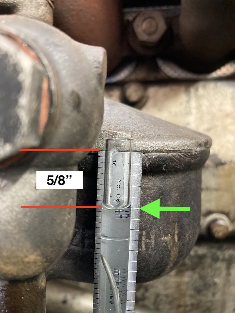 It should also be noted that the carburetor itself is horizontal in the vehicle-installed position, even though the engine is inclined at 3.25 degrees to horizontal. The intake manifold flange is opposite-angled 3.25 degrees to produce the horizontal mounting condition when the carburetor is installed on the engine, and is in the chassis. |
||||||
| *Note: Per the original 1928-31 Ford Service Bulletins and Instruction Books, the Model A GAV (Gas Adjusting Valve) should only be opened a maximum of 1/2 turn for starting and warm-up, and not be operated at more than 1/4 turn open thereafter. In the case of modern recommended jet flow rates, some configurations are sized to run generally leaner than original, but allow greater compensation by using the GAV more liberally. |
||||||
Original Model A Ford Jet Flow Rates | ||||||
| Flow Rate Ford Specifications cc's/min (ml/min) Thread Size |
Venturi A-9586 |
Throttle Plate A-9585 5-40 USF #4 Oval Head |
Idle Jet A-9542 M5x0.75 10-34 USF |
Main Jet A-9534 M5x0.75 10-34 USF |
Comp Jet A-9575 M5x0.75 10-34 USF |
Cap Jet A-9538 M5x0.75 10-34 USF |
| Jan - Jun/Sep 1928 Double Venturi Inline Main & Cap Jets No Secondary Well Ford Drawing & S.B. Normal Altitude (@ 1 Meter Head Pressure) (39.4" head pressure) |
Primary: 24 mm ID 0.945" Secondary: 10 mm ID 0.394" |
1927 (un)marked '20' degrees 1928 Marked '18-1/2' degrees Used with round idle Priming Hole. |
Marked '10' 3-5/64" OAL Used with DV lower casting only. |
148 - 152 Marked '19' (Zenith 30036A) (0.0374") |
139 - 143 Marked '18' (Zenith 30047) (0.0354") |
Marked '19' (Zenith 30085) (orifice at bottom) (0.0365" to 0.0380") |
| June - Sept 1928 Single Venturi @ SV Introduction Inline or Offset Main & Cap Jets with Secondary Well Ford Drawing & S.B. Normal Altitude (@ 37-1/4" Head Pressure) |
21.5 mm ID 27/32" 0.843" |
Marked '18-1/2' degrees Used with keyhole-shaped idle Priming Hole. |
45 - 55 Marked '11' 3" OAL (Zenith 30056A) (0.55mm) (0.0216" ± 0.002") 59.5mm siphon |
157 - 161 Marked '19.5' |
157 - 161 Marked '19' (Zenith 30048A) (0.95mm / 0.0374") |
Marked '21' |
| March 1930 Single Venturi Specs Update Offset Main & Cap Jets with Secondary Well Ford Drawing & S.B. Normal Altitude (@ 37-1/4" Head Pressure) |
21.5 mm ID 27/32" 0.843" |
Marked '18-1/2' degrees Used with keyhole-shaped idle Priming Hole. |
45 - 55 Marked '11' 3" OAL (Zenith 30056A) (0.0216" to 0.0236") 2-5/16" siphon |
165 - 169 Marked '20' (Zenith 30036B) 1930 #63 / #62 (1mm / 0.0394") 1931 #60 (0.0394" to 0.0409") |
157 - 161 Marked '19' (Zenith 30048A) (0.95mm / 0.0374") |
180 - 190 Marked '20' (Zenith 30086A) (orifice at top) #60 (0.0394" to 0.0409") |
| Higher Altitude 5000+ ft above sea level Single Venturi with Secondary Well Ford Drawing (@ 37-1/4" Head Pressure) |
21.5 mm ID 27/32" 0.843" |
Marked '18-1/2' degrees Used with keyhole-shaped idle Priming Hole. |
45 - 55 Marked '11' 3" OAL (Zenith 30056A) (0.0216" to 0.0236") 2-5/16" siphon |
157 - 161 Marked '19.5' |
157 - 161 Marked '19' (Zenith 30048A) (0.95mm / 0.0374") |
180 - 190 Marked '20' (Zenith 30086A) #60 (0.0394" to 0.0409") |
Several Current Model A Recommendations to Consider | ||||||
| Flow Rate Recommendations cc's/min (ml/min) (@ 36" Head Pressure) |
Venturi A-9586 |
Throttle Plate A-9585 |
Idle Jet A-9542 (manifold vacuum) |
Main Jet A-9534 (venturi suction) |
Comp Jet A-9575 (atmospheric pressure on fuel, both sides) |
Cap Jet A-9538 (venturi suction) Cap discharges Comp + GAV |
| David Renner 2022* *ethanol fuel era |
21.5 mm ID 27/32" 0.843" |
Marked '18-1/2' |
50 - 60 target enables greater idle air mixture control |
150 target enables greater GAV utilization |
150 target enables greater GAV utilization |
300 target enables greater GAV contribution |
| David Renner 2022* Higher Elevation 5000+ ft above sea level *ethanol fuel era |
21.5 mm ID 27/32" 0.843" |
Marked '18-1/2' |
50 - 60 target enables greater idle air mixture control |
125 -129 target enables greater GAV utilization |
125 -129 target enables greater GAV utilization |
300 target enables greater GAV contribution |
| Chris Pelikan 2010* *ethanol fuel era |
21.5 mm ID 27/32" 0.843" |
Marked '18-1/2' |
44 - 48 | 150 - 160 | 155 - 165 | 170 - 190 |
| Al Blatter 1983 NOS Jets = (full rich) |
21.5 mm ID 27/32" 0.843" |
Marked '18-1/2' |
46 - 50 |
159 - 163 |
152 - 156 |
176 - 180 |
Ethanol-Blended Fuels and Zenith TuningMany older published jet flow recommendations from the pre-ethanol era appear to be a bit on the 'too lean' side of the equation for use with todays lower energy ethanol-blended fuels. However, those older jet flow rates may be more acceptable today at higher elevations, or for use with current non-ethanol 'recreational' gasoline. The Flow Rate Recommendations in the table above incorporate modifications to more effectively utilize today's ethanol-blended fuels, as well as work with ethanol-free 'recreational' gasoline. The specific problem with a "too lean" Idle Jet flow target is that although you can always effectively 'add more air leak' (resulting in less fuel) with the Idle Air Mixture Needle and make the mixture more lean, there is no opposite adjustment capability to 'add more fuel' to richen the idle air-fuel mixture. The only method to add any more idle fuel (needed for ethanol blends) is to enlarge the Idle Jet orifice, thus increasing its fuel flow rate and fuel consumption. Also note that the GAV in a properly restored Zenith has no effect on the idle of a warmed up engine running at proper and normal idle speeds. (<550 RPM) The GAV is a higher speed, open-throttle, fuel supply circuit acting only through the Cap Jet and the Venturi, (though it is also possible for the GAV to replenish a starving Secondary Well and Idle Jet in the case of an obstructed Compensator Jet). Running the Main Jet flow rate a little less than original is acceptable because you can also run the GAV a little more open in order to increase the total fuel quantity to the Cap Jet if needed. But this method only works if the Cap Jet is also sized to flow the combined Compensator + GAV fuel quantities (supplied at atmospheric pressure). Many published Cap Jet flow targets from the pre-ethanol era may be too small to support that method of operation at higher speeds using today's ethanol-blended fuels. In fact, many Cap Jet flow rate recommendations in the past were even less than that of an original Zenith carburetor, thereby possibly limiting the GAV usefulness at higher loads/speeds. Also recognize that the flow through the Main Jet is progressively larger with increasing engine speed and Venturi suction, whereas the flow through the Cap Jet is mostly constant with increasing engine speed and Venturi suction. Although the Cap Jet orifice is acted on by Venturi suction effects, its direct fuel supply maximum flow rate is affected only by atmospheric pressure in the float bowl and above the Secondary Well, and is unaffected by manifold vacuum, Venturi suction effects, or by the carburetor body vent hole. The Compensator Jet flow to the Cap Jet is metered by the Compensator Jet orifice size, and by the atmospheric pressure in the float bowl on the Compensator Jet inlet side, balanced by the atmospheric pressure also on the Compensator Jet outlet side (via the vacuum breaker hole at the top of the Compensator/Secondary Wells, and the carburetor body vent hole and atmospheric pressure above the fuel in the Compensator/Secondary Wells). Additionally, any fuel added to the Cap Jet supply through the GAV needle/seat bypasses the Compensator Jet orifice restriction, and is also controlled only by atmospheric pressure in the float bowl, and by the amount the GAV needle and seat is opened. | ||||||
Fuel Characteristics and Performance CommentsFirst Things First!Some people seem to conflate 'Leaded and Unleaded' fuels with 'Non-ethanol and Ethanol-blended' fuels! Don't be one of THOSE people! Unleaded and Ethanol-blended fuels are completely unrelated, except for their usages being due to clean air legislation. Since 1996, ALL automotive pump gas in the U.S. has been Unleaded. There are no longer any options to use Leaded gasoline in automobiles. Leaded gasoline cannot legally be be sold or dispensed for any on-road use. Additionally, the term "Regular" on an automotive pump selection does not mean 'leaded', nor does it mean 'non-ethanol'. It generally only refers to a lower octane rating fuel choice offered by that brand or station. Furthermore, the term "Unleaded" is sometimes also displayed on a pump as part of a fuel name. It is just a marketing gimmick. ALL on-road automotive gasoline blends are Unleaded! As well, Octane and Octane Rating are two different things. Octane is the alkane hydrocarbon C8H18 and is a major component of gasoline. The Octane Rating (number displayed at the pump) is the average of the Research (RON) and Motor (MON) test methods of quantifying anti-knock and fuel stability properties of the blended fuel. Fuels rated at 87 octane rating are typically called "Regular" at the pump, and 89 rating fuel is often called "Plus". The 91 and higher octane rating fuels are sometimes called "Premium", "Ultra", or "High Test" at the pump for marketing purposes. The octane RATING is NOT an indication of 'how much octane' the blended fuel contains. It IS however an indication of the tested anti-knock properties/performance of the blended fuel. A higher octane Rating doesn't change the thermal energy content of a gallon of fuel (the energy available to move a vehicle down the road). A higher octane RATING only indicates greater resistance to knock (the too-early combustion of the air-fuel mixture that causes the cylinder pressure to undesirably spike). Using a higher octane RATING fuel in your Model A Ford Zenith carburetor won't make it perform better, go faster, get better mileage, or run cleaner. Sorry, but a basic low cost 87 octane rating fuel is fine, even with your so-called 'high compression' cylinder head. E10 Ethanol-blended Fuel Usage Comments: It should be noted that various other hobbyist jet flow recommendations shown in the table below and often quoted in the hobby were from a time long before the widespread and predominant availability and use of E10 ethanol-blended fuels (typically 87, 89, 91, 93, and 95 octane rating). Use of Ethanol-blended fuel (also called oxygenated fuel) in the U.S. has increased dramatically from about 1.7 billion gallons in 2001 to about 14 billion gallons in 2022. Per the U.S. Department of Energy, E10 is sold in every state. Unleaded 87 octane rating E10 is now (2023) the most commonly used fuel in the U.S. More than 98% of U.S. gasoline now contains up to 10% ethanol in order to boost the octane rating and combustion efficiency, reduce ground level ozone levels, meet air quality requirements, and satisfy the Renewable Fuel Standard. The present near-total adoption of ethanol-blended automotive pump fuels has been steadily ramping up in the U.S. since the 2001 new vehicle model year, driven by prior Energy Policy Acts and the Clean Air Act of 1990 legislation. Ethanol-Blended Fuel Consequences: Ethanol contains about 33% less energy than pure gasoline, gallon for gallon. According to EPA research, modern vehicles will typically go 3% to 4% fewer miles per gallon on E10 blends than on 100% (ethanol-free) gasoline. Ethanol molecules contain oxygen atoms. Gasoline molecules do not. An effect of the oxygen in ethanol is that ethanol blends tend to run "leaner" in the same carburetor than pure gasoline because there is more oxygen available to the fuel-air mixture. Ethanol is also corrosive in nature due to the oxygen content. Ethanol-blended fuels are also prone to phase separation of the ethanol from the gasoline in the fuel tank and in the carburetor bowl, and the ethanol then absorbs moisture from the air. The moisture and oxygen in the ethanol contributes to fuel system corrosion, both in the tank and in the carburetor itself, affecting iron, steel, zinc, and especially aluminum (think fuel level gauge)! The ethanol also severely attacks cork gaskets and floats, as well as many older rubber compounds previously used in fuel systems. Side note: All fuel tanks will have a tendency to condense any atmospheric moisture inside, regardless of fuel type, and many people prefer to keep their fuel level in the tank topped-off to minimize this effect. For the reasons above, it is generally recommended to avoid ethanol blended fuels when possible in the Model A, and to only use non-ethanol (ethanol-free) gasoline, also commonly referred to and sold as 'recreational gasoline' (for boats, lawn equipment, etc.). Recreational gasoline is typically offered as 88 to 90 octane rating non-ethanol / ethanol-free (it is unleaded / lead-free as well). The pump dispenser must clearly state that the fuel choice is non-ethanol / ethanol-free gasoline, otherwise it is not! Depending upon jurisdiction, ethanol blends might not be labeled as such, however all non-ethanol / ethanol-free selections in the US must be so-labeled at the pump! Having stated all that, a great many Model A's are routinely run successfully on 87 octane rating ethanol-blended E10 pump gas, especially if they are driven regularly. Importantly however, NEVER use any E15 or E85 Flex Fuels in a Model A Ford! |
||||||
E15 & E85 Ethanol-blended Fuel Usage Warning:E85 Flex Fuels (51-85% ethanol-blended) as well as E15 fuels (10-15% ethanol-blended) are also now widely available, and are often labeled at pumps as "E85", "Flex Fuel", "Unleaded 88", or "Regular 88". Do not be confused! The term "Regular" or "Unleaded" on E15 fuels DOES NOT MEAN that they are non-ethanol or ethanol-free. They are actually very high ethanol content! Due to fuel system damage risks, all E85 Flex Fuels, as well as E15 "Unleaded 88" / "Regular 88" fuels are specifically prohibited by Federal law for use in any vehicles or power equipment produced prior to the 2001 Model Year. Those fuels should only be used when specifically recommended or approved by the vehicle manufacturer.  |
||||||
Older Published Model A Jet Flow Values (pre-ethanol era) |
||||||
| Flow Rate Recommendations cc's/min (ml/min) (@ 36" Head Pressure) |
Venturi A-9586 |
Throttle Plate A-9585 |
Idle Jet A-9542 |
Main Jet A-9534 |
Comp Jet A-9575 |
Cap Jet A-9538 Cap discharges Comp + GAV |
| Al Blatter 1983 Recommended Targets pre-ethanol era |
21.5 mm ID 27/32" 0.843" |
Marked '18-1/2' |
46 - 50 later years: 48 - 52 |
130 - 145 (advised 145) later years: 148 - 152 |
152 - 156 later years: 150 - 154 |
176 - 180 later years: 175 - 185 |
| Lloyd Kerr 1987 Fred Carlton pre-ethanol era |
21.5 mm ID 27/32" 0.843" |
Marked '18-1/2' |
44 - 48 | 140 - 150 | 138 - 142 | 160 - 166 |
| Steve Pargeter 2001 Ver.7 pre-ethanol era (2015 Ver.8 is unchanged) |
21.5 mm ID 27/32" 0.843" |
Marked '18-1/2' |
44 - 48 | 150 - 160 | 138 - 142 | 150 - 185 |
| Chris Pelikan 2001 pre-ethanol era |
21.5 mm ID 27/32" 0.843" |
Marked '18-1/2' |
44 - 48 | 150 - 160 | 138 - 142 | 150 - 185 |
| Rex Reheis 2004 Gordon Biggar (references Pargeter) |
21.5 mm ID 27/32" 0.843" |
Marked '18-1/2' |
44 - 48 | 140 - 150 | 138 - 142 | 150 - 185 |
| Paul Moller 1972-1985 (he recommended flow testing, but gave no flow targets) |
21.5 mm ID 27/32" 0.843" |
Marked '18-1/2' |
||||
*Pre-ethanol era is the time before the widespread and predominant availability and use of E10 (87/89/91/93/95 octane rating) ethanol-blended fuels in the US.
E85 Flex Fuels as well as E15 (88 octane rating) ethanol-blended fuels are also now often available.
E15 is often labeled at pumps as "Unleaded 88", or "Regular 88".
NEVER use any E85 Flex Fuel or E15 fuel in a Model A Ford!
Many 'Carburetor' Problems Are Actually Electrical
Electrical System:
- Model A battery cable is laying/rubbing across the top of the brake pedal rod.
Worn cable insulation can cause an intermittent short-to-ground during braking, and can cause momentary ignition failure when applying the brakes. - Spark Plugs are dirty or have incorrect gap.
Clean and set spark plug gaps to 0.035" - Distributor contact points are dirty or have incorrect gap.
Clean and set ignition point gap to 0.022" on new points, 0.020" on used points. - Wire between the distributor contact point stud under the top plate and the lower distributor plate and condenser is frayed and can cause an intermittent short-to-ground during spark advance movement.
Remove the distributor top plate and check the condition of the wire.
See linked page below for recommended wiring and replacement. - Ignition spark is not correctly timed.
(Re)time the distributor contact points according to the Model A (or Model B if appropriate) Ford Instruction Book or Ford Service Bulletins instructions, after setting the contact point gap and/or inspecting the internal distributer wiring. - Coil to Distributor Cap high tension wire is not seated properly.
Check condition and fit of coil wire terminals in the coil nipple and in the distributor cap. Solder the terminal end connector to each end of the coil wire. - Distributor cap carbon button is worn, damaged, or missing.
Check condition of the carbon button in the distributor cap. - Distributor rotor top contact/spring is not contacting the carbon button consistently.
Check to ensure some spring preload on cap before attaching distributor cap and body metal spring clips. - Ignition coil is not wired with correct polarity.
For a positive ground system, the negative (-) coil terminal is connected to either of the two terminal box brass studs.
The positive (+) coil terminal wire goes to the ignition switch, through the switch, and then to the distributor movable contact point. Coil primary ground path is completed when the ignition points in the distributor close, allowing the coil to energize.
The coil high tension secondary fires when the contact points in the distributor break 'open'. - Throw away your timing lights, pulley indicators, special wrenches, over-thought timing gadgets, and magic beans!
Won't Idle Properly and/or Stalls When Stopping
Fuel System:
- Did you verify you have clean fuel, in a clean vented tank, and free flow out the line at the carburetor while the tank valve is open? It should piss like a race horse, technically speaking!
Okay, let's find out why it dies on stopping, or won't idle properly! - First, verify the fuel line is not extended too far into the upper carburetor casting, contacting the Fuel Strainer and limiting flow volume into the carburetor. The compression ferrule ('olive') should be no more than 1/8" from the end of the tubing.
- Verify the Fuel Strainer screen (inside the non-sidebowl carburetor) is not clogged with rust or debris, limiting flow volume to the float fuel valve and carburetor bowl.
- Verify that the throttle shaft lever on the carburetor has a full range of travel when actuated by the accelerator control and the hand throttle.
Ensure that the carburetor throttle shaft lever fully returns to the stop position, and can be opened to the wide-open throttle position when installed on the engine and in the car.
Ensure the use of the correct length throttle control rod.
Loosening the clamp and rotating the mast jacket on a 2-Tooth steering column will allow some adjustment.
It may be necessary to bend the long forged steel arm of the throttle control assembly where the throttle control rod attaches. - Verify that the Fuel Level (not the float height) in the float bowl is correct.
Measure and set the fuel level 5/8" ± 1/32" below the fuel bowl gasket surface using an externally visible sight gauge mounted to the drain plug hole. Use fuel or mineral spirits, not water, to measure the fuel level. Vary the thickness of the fuel valve gaskets to change the float height and fuel level. Do not bend the float in any way. - Idle RPM is set too low (<350) to recover after the (open) throttle is suddenly released/closed.
- Idle RPM is set too high (>550) and the engine is not actually running on the idle circuit or at idle speed. (~450 RPM idle target)
The throttle shaft lever adjustment screw and plate are set too far open, and the engine is actually "fast idling" on the fuel and air from the Cap Jet and through the Venturi, not the Idle Jet and Air Mixture Screw (Needle) circuit.
In this fast idle condition, the GAV will have some effect on the (fast) 'idle' quality. Though the engine is running, this is not the normal or intended idle RPM condition. - The Idle Air Mixture Screw (Needle) is improperly adjusted and the idle mixture is too lean (too much air/too little fuel).
- The fit of the closed-position of the throttle plate in the casting bore is poorly aligned.
Back off the throttle shaft lever stop screw, loosen two throttle plate screws, and reset the fit of the plate in the bore in the fully closed position. Retighten the plate screws. Re-establish the correct idle speed with the idle stop screw on the throttle shaft lever. - A vacuum leak to the atmosphere is present at either/both ends of the throttle shaft in its fit to the shaft bores in the upper casting.
- A vacuum leak to the atmosphere is present at the carburetor-to-manifold flanges or gasket.
- The Idle Jet siphon tube is cracked or damaged, or has a loose fit to its threaded upper fitting.
These conditions can cause a vacuum leak, making it unable to draw fuel up the tube. - The Idle Jet orifice/flow is too small/lean, especially for ethanol mix fuels.
Ethanol-blended fuels have lower energy per volume compared to gasoline and need larger fuel flow rates. - The Idle Jet orifice is obstructed with rust or dirt.
- The Idle Fuel aperture (also called the 'Priming Hole') in the upper casting throttle bore is obstructed with rust or dirt.
- The Idle Fuel and Air passages in the upper casting are obstructed with rust, dirt, insect nests, spider webs, or cocoons.
- The two small orifices in the bottom of the brass Secondary Well (on Model A) are partially plugged with rust or dirt. This causes the idle jet supply (Secondary Well) to run dry.
- Compensator Jet orifice is obstructed, starving both the Secondary/Idle Well and the Cap Jet.
- The brass Secondary Well (on Model A) is obstructing or is contacting the Compensator Jet.
Use the 3rd (newest) Ford brass Secondary Well design to ensure clearance for Compensator Jet flow into the Secondary/Idle Well. See link in the list below. - A vacuum leak is present at any of the various vacuum line connections of the wiper motor.
- A vacuum leak is present at the intake manifold-to-block gasket.
No Power at Speed and/or Speed is Limited
Fuel System:
- Did you verify you have clean fuel, in a clean vented tank, and free flow out the line at the carburetor while the tank valve is open? It should piss like a race horse, technically speaking!
Okay, let's find out why it has no power at speed, or is speed limited! - First, verify the fuel line is not extended too far into the upper casting, contacting the Fuel Strainer and limiting flow volume into the carburetor. The compression ferrule ('olive') should be no more than 1/8" from the end of the tubing.
- Verify the Fuel Strainer screen (in the non-sidebowl carburetor) is not clogged with rust or debris, limiting flow volume into the float fuel valve and carburetor bowl.
- Verify that the throttle shaft lever on the carburetor has a full range of travel when actuated by the accelerator control and the hand throttle.
Ensure that the carburetor throttle shaft lever fully returns to the stop position, and can be opened to the wide-open throttle position when installed on the engine and in the car.
Ensure the use of the correct length throttle control rods at the carburetor (10-5/8") and at the hand throttle (5-7/8"). Those are center-to-center dimensions.
Loosen the clamp at the bottom of the mast jacket on a 2-Tooth steering column to allow it to rotate. This will allow some adjustment.
It may be necessary to bend the long forged steel arm of the throttle control assembly where the throttle control rod attaches. - Verify that the Fuel Level (not the float height) in the float bowl is correct.
Measure and set the fuel level 5/8" ± 1/32" below the fuel bowl gasket surface using an externally visible sight gauge mounted to the drain plug hole. Use fuel or mineral spirits, not water, to measure the fuel level. Vary the thickness of the fuel valve gaskets to change the float height and fuel level. Do not bend the float in any way. - Ensure the Main Jet orifice is not obstructed with rust or dirt.
- Ensure the float bowl passage to the Main Jet is not obstructed with rust or dirt.
- Ensure the float bowl passage to the GAV is not obstructed with rust or dirt.
- Ensure the Compensator Jet orifice is not obstructed, starving both the Secondary/Idle Well and the Cap Jet.
- Ensure the Cap Jet orifice is not obstructed with rust or dirt.
- Ensure the lower casting passage between the GAV and Secondary Well/Cap Jet is not obstructed with rust or dirt.
- Verify that an actual Compensator Jet is installed in the float bowl, and is not mixed up with a GAV Needle Seat in its place (common mistake, very similar appearance).
- Verify that the Compensator Jet in the float bowl is not contacting the Brass Secondary Well, blocking flow through the Compensator Jet.
There were primarily three different brass wells, and the current reproduction will work in all carburetor iterations. - Ensure the GAV Needle is not jammed into the brass GAV Needle Seat, causing the obstructed seat to rotate with the needle (unscrewing from the casting) as the choke rod is rotated, thus defeating the GAV function.
- Verify that an actual GAV Needle Seat is installed in the base of the lower casting GAV bore, and is not mixed up with a Compensator Jet in its place (common mistake, very similar appearance).
A Word About Rebuilders, YouTube Videos, Social Media, "Celebrity" Endorsements, etc.
Be wary of unverified advice and peanut gallery comments found online regarding Model A Ford Zenith carburetor theory of operation, performance, and rebuilding! There is a vast amount of incorrect and ill-advised Zenith info and opinions being peddled on internet message boards, YouTube videos, social media posts, and eBay listings.
Those postings may be well-intentioned but are very often factually wrong, mistaken, misleading, and in some cases border on nonsense. Ford Garage makes a very strong effort to stay centered on verified facts from primary sources, and welcomes constructive feedback on potential errors or omissions, and on items deserving further discussion and clarification.
The vast majority of Zenith information presented here on Ford Garage comes directly from original era Ford and Zenith detail part drawings and 1930's OEM catalog information, Zenith Service Manual publications from the early 1930's, from various Dykes carburetor books and publications from the 1930's, and from an extensive collection of Model A and B Ford Zenith carburetors and Zenith rebuilding experience, as well as from discussion and collaboration with a few knowledgeable Zenith experts.
If you are looking online for expert knowledge, insight, and advice on the Model A and B Ford Zenith carburetors, as well as quality Marvel and Model B Zenith new parts and services, new flow-tested Zenith jet sets, and also nicely designed fuel level sight gauges, contact David Renner at Renner's Corner in Manchester, Michigan, linked in the list below.
If you are looking for a very experienced Zenith carburetor rebuilder, you should consider Steve Becker at Bert's Model A Store in Denver, Colorado for knowledgable and reliable work, according to many testimonials.
If you are looking for good Zenith rebuilding books, all of the 'classics' from the Model A hobby authors of the 1960's-90's contain many factual errors and incorrect conclusions, and can easily lead you astray if you accept everything at face value. A combination of Gordon Biggar/Rex Reheis' (OOP) and Steve Pargeter's (Version 8) most recent books offer the most accurate and useful Zenith hobbyist information published in the last 50 years.
Additionally, Rex's coverage of the Model B Zenith carburetor is about the best you will be able to find in recent print for that specific carburetor. Also, David Renner and George DeAngelis authored a number of very good Model B Zenith articles in Secrets of Speed magazine in the 1990-2000's.
In MARC's and MAFCA's bi-monthly club magazine publications, Steve Schmauch's recent (2017-2023) series of Model A Zenith articles in The Restorer magazine on Zenith and Holley casting differences and identification are very comprehensive, insightful, and helpful. Many other Model A Zenith carburetor magazine articles, past and present, have been an unreliable mixture of wheat and chaff, requiring your own knowledge and capability to distinguish between the two.
The MARC/MAFCA jointly-published Restoration Guidelines & Judging Standards manual contains the final word on carburetor details and authenticity for judging purposes, and is an invaluable resource for people who seek to achieve as much authenticity and correctness of parts and appearances as possible.
The Zenith web sites of Paul Modlin and Chris Pelikan (now maintained by Bert's) are both very helpful and are linked in the list below.
More related information on Ford Garage:
- For more Model A & B related information, use the Site Search box at the top or bottom of this page.
- Model A Zenith Carburetor Theory of Operation
- Model A Zenith Carburetor Numbering
- Model A Zenith Carburetor A-9545 Secondary Well Variations
- Model A Zenith Carburetor Float Mass and Performance Details
- Model A Zenith Carburetor GAV Wrench
- Model B & 46 Zenith Carburetor Parts Catalog Illustrations
- Model B & 46 Zenith Carburetor Assembly Drawings
- Model B & 46 Zenith Carburetor Float Mass and Performance Details
- Model B & 46 Zenith Float Fuel Valve Orifice Details
- Model B & 46 Zenith Carburetor Power Jet Circuit
- Model B & 46 Zenith Carburetor Power Jet Tube
- Model B & 46 Zenith Carburetor Power Jet Tube Instructions
- Model B & 46 Zenith Carburetor Catalog Data
- Model B & 46 NOS Zenith Carburetor
- Model B & 46 Zenith Carburetor Upper Casting Variations
- Model A & B & V8 Spark and Throttle Control Rods
- Model A & B & V8 Renner's Corner, Quality Model A & B Carburetor Parts and Advice
- Model A Paul Modlin's Zenith Carburetor Animations on Model A Basics.com
- Model A Chris Pelikan's Zenith Carburetor MasterClass on Model-A.org
- Model A & B Throttle Shaft Bushing Install ~ Randall Strickland on YouTube
- Model A Distributor Lower Plate Wiring Solution
- Model A & B & V8 Vacuum Gauge Tuning from ARSCO
- Model A & B & V8 World War II Training Film: Automotive Troubleshooting. 1942 on YouTube
- Model A & B & V8 World War II Training Film #497: Mechanics, Champion Ignition and Spark Plug. c. 1941-1945 on YouTube
Vince Falter
May 2005
