
Model A & B
Ford Garage
Camshaft to Crankshaft Gear Alignment
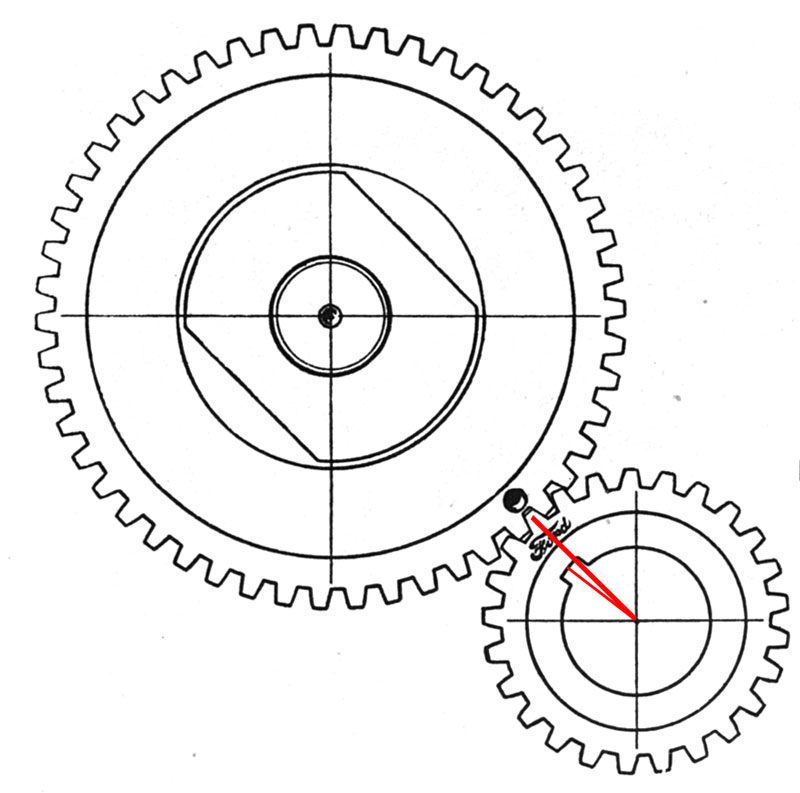
The illustration below shows the relationship of the engine camshaft and crankshaft gear mesh. The proper mesh of the gears assures that the valve opening and closing is properly timed to the crankshaft and piston position.
The crankshaft and camshaft timing gears are common and interchangeable between both the Model A and Model B engines.
The proper mesh of the two timing gears assures proper relationships between the valves and pistons.

 fordgarage.com
This dimple has two purposes:
- It is used to indicate proper mesh alignment with the crankshaft gear.
- It is used together with the timing pin and the hole in the timing gear cover to properly locate the Number 1 piston at top dead center (TDC) of the compression stroke for setting the spark ignition timing in the distributor.
The camshaft gear can only be assembled to the camshaft in one position. The two locating dowels are slightly offset to each other to prevent improper gear installation on the camshaft. The camshaft gear has 50 helical cut teeth, and rotates at half the engine speed.
The crankshaft gear can also only be assembled to the crankshaft in one position. The locating keyway establishes the relationship of the gear to the crankshaft. The crankshaft gear has 25 helical cut teeth and rotates at engine speed.
The crankshaft gear alignment tooth is the first tooth to the right of the crankshaft keyway centerline, as shown in red in the illustration above.
 fordgarage.com
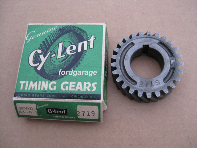
Original Ford crankshaft gears had a 'Ford' script timing mark centered on the tooth used to align to the camshaft gear. Most replacement crankshaft gears have a circle, indentation, or similar mark on the alignment tooth.
When properly meshed, the timing mark on the crankshaft gear will directly align with the dimple on the camshaft gear.
Note: When the two alignment marks are meshed as shown in the illustration above, the proper gear alignment is assured. It does not indicate TDC at that position.
The timing pin and timing gear cover must be used to locate the Model A initial ignition timing point of Number 1 piston at 0 degrees (TDC) when using a Model A timing cover.
The initial Model B distributor timing point of 19 degrees BTDC is indicated when using a Model B timing cover, shown below.
 fordgarage.com
More related information on Ford Garage:
- For more Model A & B related information, use the Site Search box at the top or bottom of this page.
- Model A & B Camshaft to Crankshaft Positioning
- Model A & B Engine Cam/Valve and Ignition/Spark Timing Discussion
- Model A & B Kwik-Way LBM Main Bearing Boring Bar Fixtures
- Model A & B Tobin-Arp Main Bearing Boring Bar Fixtures
- Model A & B LEMPCO FSU Main Bearing Line Boring Machine
- Model A & B AER Insert Main Bearing Data & Instructions
- Model A & B Camshaft Timing Gear Varieties
- Model A & B Camshaft Gear Front Timing Cover Differences
- Model A & B Original 5-Z-1832 Cam Gear Wrench
- Model A & B Camshaft Thrust Plungers
- Model A & B Original Ford Camshaft Details
Vince Falter
July 2015
