

Model A & B
Ford Garage
Camshaft Specifications
Contrary to some popular beliefs, there is no evidence of multiple different Model A or Model B camshaft profiles or timing designs on record at the Benson Ford Research Center for US production. There was a single profile design for both Model A intakes and exhaust lobes, and different profile designs for Model B intake and exhaust lobes.
It is true that some other camshaft designs were released worldwide in England, Germany, and the Soviet Union for small bore Model A and B engines, and for later Model B engine derivatives produced through at least the 1940s.
There was a camshaft and valve push rod (popularly called a tappet or lifter) design for the Model A, and a somewhat different design for the Model B. The stories of multiple different Model B camshaft grinds and profiles are not supported by original Ford drawing and release records or Ford technical publications.

 fordgarage.com
The Model A camshaft drawing A-6250-A1 was obsoleted on August 2, 1932, and was superseded by the production Model B camshaft B-6250 (along with the B-6500 push rod) for Model A Ford Service use.
The Model B camshaft B-6250 had one cam profile design for the intake lobes, and a different cam profile for the exhaust lobes, making a single complete camshaft design.
There were no dimensional changes of the Model B lobe profiles or lobe timing of the camshaft throughout its Production and Service life, and no apparent evidence exists that it was superseded by a different camshaft part number or design level.
Compared to the Model A lobe profile, the Model B camshaft design has a more pointed lobe design (smaller nose radius) and is known for rapid and considerable wear on the nose or tip of the lobe.
This nose wear quickly and significantly reduces the effective lift of the cam lobe (and valve). Worn, rounded, and well-used cams may perhaps be mistaken as a 'different' lobe design when compared to a new or an unused cam still having a sharp cam nose profile.
Accelerated wear on the nose of the lobe reduces the overall lift of the lobe and valve, and diminishes the rate of valve seat opening of the valve. Net result: Loss of torque and power.
The various lift numbers presented in internet forum discussions are frequently wrong, and valve and lobe numbers are often conflated by popular storytellers.
All US Model A camshafts originally had a lobe lift of 0.302 inches for both the intake and exhaust lobes.
All US Model B camshafts originally had an intake lobe lift of 0.334 inches and an exhaust lobe lift of 0.341 inches.
Resulting valve lifts are a function of the associated recommended clearance gaps for each lobe profile design.
The chart below is accurate Ford-published technical information, despite some common public misconceptions and message board insistence to the contrary!
Ford-Published Camshaft Specifications:
| Camshaft Specification | Model A A-6250 |
Model AF AF-6250 |
Model B B-6250 |
British BE BE-6250-B |
Model BF BF-6250 |
Units |
|---|---|---|---|---|---|---|
| Valve Open Duration | 236 | 244 | crankshaft degrees | |||
| Lobe Separation Angle | 112 | 114 | camshaft degrees | |||
| Valve Overlap Angle | 12 | 16 | crankshaft degrees | |||
| Required Minimum Push Rod Base Diameter |
1.117 | 1.187 | inches | |||
| Push Rod Original Length | 2.486 | 2.518 | inches | |||
| Intake Lobe Design Lift | 0.302 | 0.334 | 0.338 | inches | ||
| Intake Valve Design Clearance (gap) | 0.015 | 0.015 | 0.015 | inches | ||
| Intake Valve Lift | 0.287 | 0.319 | 0.324 | inches | ||
| Intake Valve Opens BTDC | 7.5 | 8 | 30 | crankshaft degrees | ||
| Intake Valve Closes ABDC | 48.5 | 56 | 78 | crankshaft degrees | ||
| Exhaust Lobe Design Lift | 0.302 | 0.341 | 0.338 | inches | ||
| Exhaust Valve Design Clearance (gap) | 0.015 | 0.022 | 0.017 | inches | ||
| Exhaust Valve Lift | 0.287 | 0.319 | 0.322 | inches | ||
| Exhaust Valve Opens BBDC | 51.5 | 56 | 74 | crankshaft degrees | ||
| Exhaust Valve Closes ATDC | 4.5 | 8 | 26 | crankshaft degrees |
| Piston Position | |
|---|---|
| BTDC | Before Top Dead Center |
| ABDC | After Bottom Dead Center |
| BBDC | Before Bottom Dead Center |
| ATDC | After Top Dead Center |
From the table above, it can readily be seen that the primary differences between the Model A and Model B camshafts are that the Model B intakes and exhausts have higher lobe and valve lifts, and longer valve open duration compared to a Model A.
In order to combat burned exhaust valves and seats experienced on the Model A, the Model B exhaust lobe was redesigned for a larger tappet (push rod) clearance (gap) to allow for more exhaust valve thermal expansion, and more dwell time on the valve seat in the block for increased valve head cooling.
The cooler running intake valve retained its smaller design gap.
This increased exhaust valve clearance change, in turn, drove a different ramp design on the exhaust valve cam lobe profile in order to smoothly engage the valve and lift it with minimal noise and lobe wear. The Model B intake valve lobe was also redesigned for higher lift, but with smaller tappet clearance than the exhaust.
Note that the Model B design has different intake and exhaust lobe design lifts, but has equal actual intake and exhaust valve lift.
The explanation lies in the different design tappet clearances (gap/valve lash) between intake and exhaust.
Push Rod-to-Valve Design Clearances:
| Ford Design Tappet Clearance (inches) | ||
| Camshaft Design |
Intake Valve Clearance (gap) |
Exhaust Valve Clearance (gap) |
| Model A A-6250 |
0.015 | 0.015 |
| Model B B-6250 |
0.015 | 0.022 |
| Model BF BF-6250 |
0.015 | 0.017 |
Push Rod Diameters:
It should also be noted that Ford designed the Model B push rod (tappet) base diameter size and length to match the Model B cam lobe profiles. Ford also issued Service Bulletin warnings not to mix and match Model A and B camshafts and tappets.
 fordgarage.com
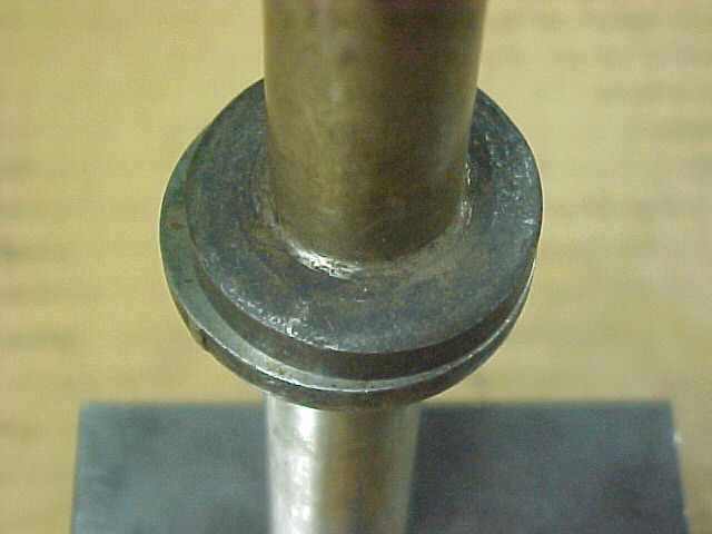
Pictured above is a comparison of the larger (1.187") base diameter of a Model B Ford NOS B-6500 solid tappet on the bottom, with a smaller (1.117") base diameter Model A NOS A-6500 solid tappet on the top.
In addition, the Model B tappet is 0.032 inches longer than the Model A tappet.
(Note: the 1932 Ford Service Bulletins illustration mistakenly has the labeled length dimensions for the Model A and Model B tappets reversed, though the tappet illustrations are correctly identified)
Only use the 1.187 inches base diameter tappets with any original Model B camshaft.
The inferior ~1.000 inches (or less) undersize base diameter (jam-nut) tappets on the market should never be used with an original Model B camshaft.
The use of those too-small 1.000-inch tappets can result in severe damage to both themselves and the camshaft lobes.
This higher valve lift and longer open duration provided by the Model B cam allows for better filling, evacuating, and breathing of the cylinders, and results in increased torque and power.
Based on the geometric lobe profiles of the cam, a Model A (or B) cam cannot be "reground" to achieve both its original lift and duration from the available metal.
A cam re-grinder could restore either original lift or duration, one or the other or some compromise, but not both.
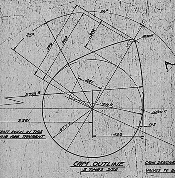
The pics below are excerpts from the original Model A camshaft drawing A-6250-A1 for illustration purposes.
 fordgarage.com
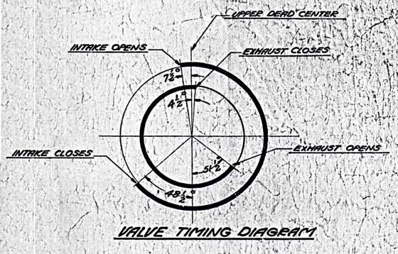 fordgarage.com
The Model A and B information cited above was compiled from the following original Ford detail drawings at the Benson Ford Research Center:
A-6250-A1 dated 8-2-32
B-6250 dated 11-11-31
B-6250 dated 1-24-33
More related information on Ford Garage:
- For more Model A & B related information, use the Site Search box at the top or bottom of this page.
- Model A & B Valve Tappet Adjustment ~ Rule of Nine
- Model A & B Camshaft Timing Gear Varieties
- Model A & B Camshaft to Crankshaft Gear Alignment
- Model A & B Camshaft to Crankshaft Positioning
- Model A & B Engine Cam/Valve and Ignition/Spark Timing Discussion
Vince Falter
January 2004
